Mode-locking
The second operating technique is completely different. This time, the laser oscillator is left to reach a steady state and the oscillation in the cavity is not blocked. However, the cavity is prevented from filling with photons everywhere at the same time: only a packet of photons is allowed to propagate in the cavity. This pulse lasts for a shorter time than a round trip in the cavity. In other words, its spatial extension is markedly shorter than the length of the cavity.
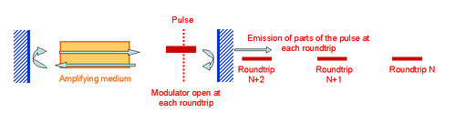
The method used to obtain these operating conditions consists in using a rapid light modulator that can chop the light in the cavity into periods of exactly the same length as a round trip. Thus, only those photons allowed to pass through the modulator in its on-state will be amplified and will always find the modulator in this state after each round trip. The other photons elsewhere in the cavity will be subject to losses when they travel through the modulator (Figure 20).
![[zoom...]](javascript:window.open(%22../res/fig20_1.jpg%22,%22_blank%22,%22width=%22+Math.min(800,screen.availWidth)+%22,height=%22+Math.min(600,screen.availWidth)+%22,left=%22+(screen.availWidth-800)/2+%22,top=%22+(screen.availHeight-600)/2+%22,scrollbars=yes,resizable=yes%22)?void(0):void(0))
Generally, the pulses last for a much shorter time than a round trip in the cavity. They are limited by the Fourier transform of the spectrum emitted by the laser: the wider the spectrum, the shorter the pulse. This means that if the amplifying medium is exceptionally wide (for example the titanium-doped sapphire has a spectral width greater than 300 nm), then the pulse generated will be only several femtoseconds long.
Figure 20 shows only a single pulse travelling in the cavity. However, a pulse train can be seen leaving the laser, generated each time the pulse hits the output mirror. The pulse repetition period corresponds to the cavity round-trip time (typically several nanoseconds).
The average power of a mode-locked laser is of the same order of magnitude as that of continuous-wave lasers. In fact, in contrast to Q-switched lasers, these can also reach a steady state like continuous-wave lasers. The fundamental difference is that the stimulated photons are condensed in a packet rather than spread all around the cavity. During one round trip, only one laser pulse is emitted via the output mirror. The pulse energy is thus equal to the average power multiplied by the duration of a round trip. Generally, these energies are of the order of several nanojoules.
The term “mode-locking” comes from the analysis of the various frequencies. A laser operating under these conditions will emit over several different frequencies due to the rapid modulation of the modulator. They are also imposed by the optical cavity, spaced out by
 : the longitudinal modes of the cavity.
In fact, contrary to what common sense would predict, the longitudinal modes interfere even if they have different frequencies because they co-exist spatially. For example, if the laser emits continuously at two frequencies separated by
 , the light output due to interference of the two waves will be modulated by a sinusoidal term of frequency
 . This modulation is generally very rapid (a few nanoseconds for a metre-long cavity). It can only be detected by sufficiently sensitive equipment (a fast photodiode and a rapid oscillator). The phenomenon is known as beating and results from the interference of beams with different frequencies.
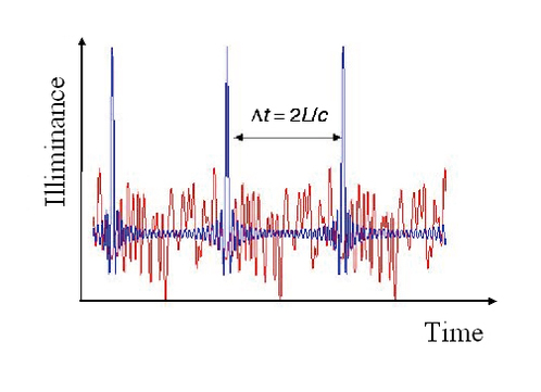
When a large number of frequencies are emitted by the laser, the beat signal becomes quite complex. Its shape depends on the relative phase of the waves with different frequencies. However, the beat signal has a very regular shape in one particular case: when all the waves emitted by the cavity are in phase. Then, there are certain times and spots in the cavity where all the waves beat in phase and the interference signal is thus very powerful (Figure 21).
![[zoom...]](javascript:window.open(%22../res/fig21_1.jpg%22,%22_blank%22,%22width=%22+Math.min(800,screen.availWidth)+%22,height=%22+Math.min(600,screen.availWidth)+%22,left=%22+(screen.availWidth-800)/2+%22,top=%22+(screen.availHeight-600)/2+%22,scrollbars=yes,resizable=yes%22)?void(0):void(0))
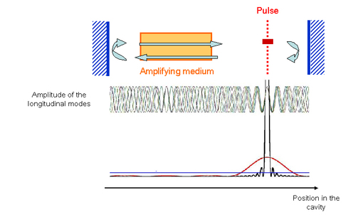
When the longitudinal modes are in phase, there is only one place in the cavity where the electric fields add together constructively. Everything occurs as if a pulse was travelling inside the cavity, just as described at the beginning of this section (Figure 22).
![[zoom...]](javascript:window.open(%22../res/fig22_1.jpg%22,%22_blank%22,%22width=%22+Math.min(800,screen.availWidth)+%22,height=%22+Math.min(600,screen.availWidth)+%22,left=%22+(screen.availWidth-800)/2+%22,top=%22+(screen.availHeight-600)/2+%22,scrollbars=yes,resizable=yes%22)?void(0):void(0))