The Nd :YAG laser
The whole laser is shown in Figure E8: the pumping system optics and the cavity. The photo also shows that the different components are positioned on adjustable mounts: the collimation and focal lenses can be moved along three different axes.
It is important to understand that these movements must be very precise. In fact, the beams in the Nd:YAG crystal have a radius of only
 . For the laser beam and the pump beam to be in the same place, the latter must be capable of being moved in the perpendicular plane of the optical axis with a precision of tens of microns.
The mirrors of the cavity (Nd:YAG on one side and the output mirror on the other) are mounted in supports that can be tilted. The mirrors must be aligned with great precision so that the Gaussian wave can travel back and forth indefinitely in the cavity. For the correct order of magnitude of the angular precision of the output mirror, its optical axis must cross the pumping zone in the crystal. This zone is only about a hundred microns so an adjustment to the nearest
 is needed when the output mirror is about 7 cm from the Nd:YAG. This gives an angle of 0.1 mrad

![[zoom...]](javascript:window.open(%22../res/figEC8_1.jpg%22,%22_blank%22,%22width=%22+Math.min(800,screen.availWidth)+%22,height=%22+Math.min(600,screen.availWidth)+%22,left=%22+(screen.availWidth-800)/2+%22,top=%22+(screen.availHeight-600)/2+%22,scrollbars=yes,resizable=yes%22)?void(0):void(0))
In practice, the pump beam is first collimated then aligned parallel to the bench. This defines a reference axis (the optical axis), which will be used to align the optical cavity mirrors. This is known as “co-linear” pumping where the pumping axis and the optical axis are the same.
Thus, this beam is used to adjust the two mirrors by autocollimation. Next, the pump beam is focused in the Nd:YAG crystal. By placing the output mirror at a distance shorter than the critical distance (Rc, here equal to 100 mm), the laser effect can be achieved.
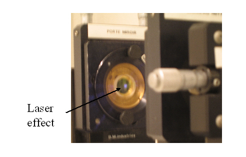
This effect is characterised by an intense light invisible to the naked eye (at 1064 nm) but detectable by a CDD camera or a simple camera as shown in Figure E9. This photo is taken from outside the optical axis. The laser photons that hit the detector are those diffused by the mirror. There are not many of them compared to the photons aligned along the optical axis. However, there are enough to create a signal on the detector of the same order of magnitude as that of the mounts and the surrounding room. In fact, if the camera had been placed in the path of the output beam, it would have been dazzled and probably damaged. Figure E9 also shows that the laser beam has a weak spatial extension compared to the size of the mirror: a radius of about 1 mm.
![[zoom...]](javascript:window.open(%22../res/figEC9_1.jpg%22,%22_blank%22,%22width=%22+Math.min(800,screen.availWidth)+%22,height=%22+Math.min(600,screen.availWidth)+%22,left=%22+(screen.availWidth-800)/2+%22,top=%22+(screen.availHeight-600)/2+%22,scrollbars=yes,resizable=yes%22)?void(0):void(0))