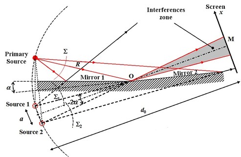
Fresnel mirrors
This device uses a primary source combined with two reflecting plan mirrors that make a slight angle
 between their planes. Their source is located at the distance
 on the mirror's edge. Each mirror gives a virtual image of the primary source and both images act as secondary sources. In the intersection area of both beams we can observe interferences. Figure 2 presents the Fresnel mirrors device.
![[zoom...]](javascript:window.open(%22../res/Fig_02_2.jpg%22,%22_blank%22,%22width=%22+Math.min(800,screen.availWidth)+%22,height=%22+Math.min(600,screen.availWidth)+%22,left=%22+(screen.availWidth-800)/2+%22,top=%22+(screen.availHeight-600)/2+%22,scrollbars=yes,resizable=yes%22)?void(0):void(0))
We demonstrate geometrically that the secondary sources are used on a circle with center
 and radius
. The screen is placed at the distance
and radius
. The screen is placed at the distance
 from the secondary sources, parallel to the sources plane. The secondary sources are quantity
 away . We recognize that we have to process the interferences between two spherical wavefronts emitted by both secondary sources. . In all point
 , the interferences are written
And in the case of the parabolic approximation where
 ,
,
As the angle
 is small, we have the triangle
 :
:
So comes :
And the interfringe is :
To define the fringes's geometric shape, we will determine the place of the points for which the phase is constant, which leads to
 , as the other magnitudes are set by the circuitry geometry. The fringes are vertical, perpendicular to the figure plane, and regularly spaced from the interfringe
 .
.