Digital holography device
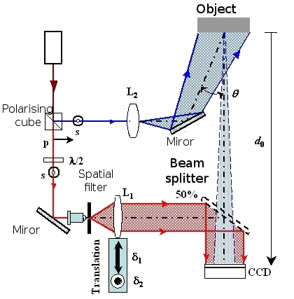
The experimental device for recording the hologram is a Mach-Zehnder-type interferometer (figure 20).
![[zoom...]](javascript:window.open(%22../res/Fig_20_2.jpg%22,%22_blank%22,%22width=%22+Math.min(800,screen.availWidth)+%22,height=%22+Math.min(600,screen.availWidth)+%22,left=%22+(screen.availWidth-800)/2+%22,top=%22+(screen.availHeight-600)/2+%22,scrollbars=yes,resizable=yes%22)?void(0):void(0))
The laser beam is split into two beams using beam splitter a cube. Thus, an object beam and a reference beam are obtained from the same monochromatic source. The half-wave plate placed at the laser source allows for the flux of the object and reference beams to be adjusted. The object beam is expanded by the lens L2 so that it lights up the object . The angle of illumination of the object is adjusted by the rotation of a reflecting mirror . Then the object diffracts a wave towards the CCD-type sensor.
By this example, we can see that using digital holography it is only possible to record transmission holograms.
The reference beam is formed by a spatial filtering system: the beam is focused by a microscopic lens in a pinhole, the unwanted angular frequencies caused by slight deviation or energy distribution faults are gotten rid of. Thus, at the exit of the pinhole, we have a light source which is considered as ‘pinpointed' giving a spherical wave form. The ‘pinpointed' source is located at the focal phase from the convergent lens L1 thus after crossing the lens, the reference beam is collimated. The system containing the spatial filter and the convergent lens L1 constitutes the afocal system which allows a plane reference wave to be obtained. The reference wave is partially reflected onto the CCD sensor by the beam splitter (50%).
The reference wave and the object wave cause interference on the CCD plate. When the interferogram, which makes up the hologram, is generated in this way, it is discretised by the CCD sensor and then recorded. The sensor encodes the information using 12 bits which represents a dynamic of 4096 grey levels.
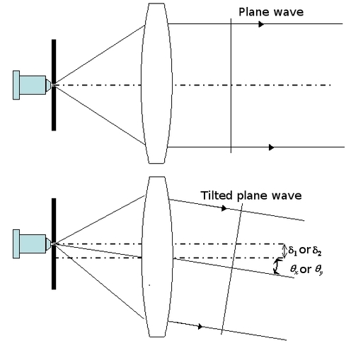
The lens L1 allows for the collimation of the reference beam. This lens has another function which is to finely regulate the angular frequencies of the reference wave. Remember that according to the Shannon theory, the maximum incidence angle is 4°. The lens L1 is mounted on a micrometrical board. As figure 21 shows, the lens board can move in two directions: horizontally by
 and vertically by
 . The aim of the vertical and horizontal movement of the lens is to tilt the reference wave at the angles
 and
and
 . Thus, the spatial frequencies of the reference wave are given by :
Figure 21 illustrates the effect of the movement of the lens.
![[zoom...]](javascript:window.open(%22../res/Fig_21_2.jpg%22,%22_blank%22,%22width=%22+Math.min(800,screen.availWidth)+%22,height=%22+Math.min(600,screen.availWidth)+%22,left=%22+(screen.availWidth-800)/2+%22,top=%22+(screen.availHeight-600)/2+%22,scrollbars=yes,resizable=yes%22)?void(0):void(0))
The CCD sensor contains
 pixels, each of a size
 .
.
The object if a 2 euro coin placed at a distance of
 from the sensor. The spatial frequencies are adjusted to
 and
and
 .
.