Calibration of a camera
Calibrating a camera consists in estimating the parameters of the model chosen to represent it. It is a kind of “parametric estimation”.
For the pinhole model (with or without distortion), this means estimating the intrinsic parameters of the camera, its position and its orientation relative to the world reference frame that has been chosen (extrinsic parameters).
Actually, the calibration of a camera is used particularly to determine its intrinsic parameters, which, as their name indicates, are intrinsic to the camera and do not change if the camera is moved. Specific methods (called localization methods) have been developed in order to determine the position of a camera according to a work reference frame when its intrinsic parameters are already known.
Usually, this calibration problem can be solved by using a specific calibration device (calibrating target) that provides known 3D points in the world reference frame.
Several calibration methods have been suggested. Throughout the years, those methods have become increasingly sophisticated to lead to a more precise and easier-to-implement calibration.
In the following part, we will describe the method that is considered nowadays as the most efficient one.
The method consists in obtaining
 images of a calibration target (plane (5.) ) composed of
 points. The target is freely moved (rotations and translations) in the field of view of the camera (see Figure 9). The calibration method is said to be of a photogrammetric type. It helps to estimate all the camera model parameters at the same time as well as the tridimensional points of the calibration target. Therefore, the geometry of the calibration target does not need to be known with precision a priori.
During the shifting of the calibration target, it is important to cover well the whole field of view of the camera in order to correctly calibrate the distortion (which is generally bigger at the images' edge rather than at their centers).
The target points may be the intersection nodes of horizontal and vertical lines (grid), the corners of a target in the shape of a checkerboard or the centers of circular patches.
The target points, which are extracted by specific image processing procedures, provide the measurements.
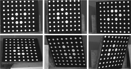
Figure 9 illustrates a 6-image sequence of a calibration target composed of 64 circular patches.
![[zoom...]](javascript:window.open(%22../res/figure_09_1.jpg%22,%22_blank%22,%22width=%22+Math.min(800,screen.availWidth)+%22,height=%22+Math.min(600,screen.availWidth)+%22,left=%22+(screen.availWidth-800)/2+%22,top=%22+(screen.availHeight-600)/2+%22,scrollbars=yes,resizable=yes%22)?void(0):void(0))
We write
 down, the coordinates of the projection of the
 point
point
 of the
 view
view
 on the camera image plane. If the distortion is taken into account, we can write from (11):
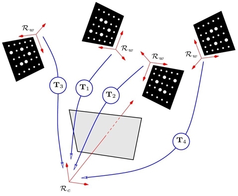
In those equations, the target reference frame is used for each view as the world reference frame. (See Figure 10).
![[zoom...]](javascript:window.open(%22../res/figure_10_1.jpg%22,%22_blank%22,%22width=%22+Math.min(800,screen.availWidth)+%22,height=%22+Math.min(600,screen.availWidth)+%22,left=%22+(screen.availWidth-800)/2+%22,top=%22+(screen.availHeight-600)/2+%22,scrollbars=yes,resizable=yes%22)?void(0):void(0))
By using (18), each projection of a tridimensional point provides two equations. Therefore, there are
 equations.
Let's count the unknown parameters left to estimate: five intrinsic parameters, seven distortion parameters in the case of a R3D1P1 model,
 extrinsic parameters (three for the rotation and three more for the translation of each rigid transformation
 ) and
) and
 tridimensional coordinates. It gives us a total of
 unknowns.
Consequently, there are
 equations and
 unknowns. If
and
are big enough (for instance if
unknowns. If
and
are big enough (for instance if
 and
and
 , there are 768 equations for 240 unknowns) ) we can estimate all the parameters minimizing the sum of the distances between the projection of the
point of the
, there are 768 equations for 240 unknowns) ) we can estimate all the parameters minimizing the sum of the distances between the projection of the
point of the
 view onto the image and the point
 extracted in the image:
with
 .
.
Minimizing (19) is a matter of non-linear optimization (called bundle adjustment) [18].
The problem is usually solved using the Levenberg-Marquardt algorithm [19], with the rotations
 expressed under a minimal form (instantaneous rotation vector, Euler angles, Bryant angles, etc.).
In order to converge, the minimization algorithm needs an initial estimate of the sought parameters: the estimation of the five intrinsic parameters of the pinhole model and of the extrinsic parameters may be obtained by analytic methods described in [20, 21]. The distortion parameters are generally initialized to zero. The initial tridimensional coordinates of the target points are those of its model which served to its creation. Given that they will be estimated again, these coordinates do not need to be known with precision, which constitutes an advantage compared with the methods requiring a precise knowledge of the calibration target used.
The minimization of (19) leads to a solution defined up to a scale factor. This factor can be determined providing the distance measured in space between two given points (2 particular points of the target for instance).