Calibration of a stereoscopic vision sensor
When we calibrate a single camera, we mainly focus on the intrinsic parameters defined by the matrix
 and, if desired, on the extrinsic parameters defined by the rigid transformation
 (localization of the camera according to the world reference frame). When we calibrate a stereoscopic vision sensor, we focus on both groups of intrinsic parameters defined by both matrix
 and
and
 and to the relative position and orientation of both cameras defined by the rigid transformation
 .
.
The aim of this sensor calibration is to allow the reconstruction of the tridimensional points observed by both cameras and is therefore very important for all of those who want to reach precise tridimensional measurements.
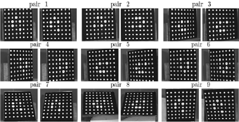
On a practical way, the process for the calibration of a stereoscopic vision sensor is similar to the process described in section 3 (Calibration of a camera) for the calibration of a camera. A target is placed in the field of view, common to both cameras, and a series of images of that target, viewed under different orientations, is taken by each camera.
For instance, Figure 13 shows a series of 9 pairs of images of a target which served to the calibration of a stereovision sensor.
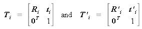
We will write down the rigid transformations
 and
and
 respectively for the left and right camera, as below:
![[zoom...]](javascript:window.open(%22../res/figure_13_1.jpg%22,%22_blank%22,%22width=%22+Math.min(800,screen.availWidth)+%22,height=%22+Math.min(600,screen.availWidth)+%22,left=%22+(screen.availWidth-800)/2+%22,top=%22+(screen.availHeight-600)/2+%22,scrollbars=yes,resizable=yes%22)?void(0):void(0))
![[zoom...]](javascript:window.open(%22../res/Eq_C_ext_32_1.jpg%22,%22_blank%22,%22width=%22+Math.min(800,screen.availWidth)+%22,height=%22+Math.min(600,screen.availWidth)+%22,left=%22+(screen.availWidth-800)/2+%22,top=%22+(screen.availHeight-600)/2+%22,scrollbars=yes,resizable=yes%22)?void(0):void(0))
They link the
 view of the target respectively to the left camera reference frame and to the right camera one. For each position of the target, we have the following relation (see Figure 14) according to (23):

![[zoom...]](javascript:window.open(%22../res/figure_14_1.jpg%22,%22_blank%22,%22width=%22+Math.min(800,screen.availWidth)+%22,height=%22+Math.min(600,screen.availWidth)+%22,left=%22+(screen.availWidth-800)/2+%22,top=%22+(screen.availHeight-600)/2+%22,scrollbars=yes,resizable=yes%22)?void(0):void(0))
Different methods permit the estimation of transformation
 .
.
The method which is usually used consists in the calibration of each camera independently, using the method described in section 3 (Calibration of a camera), in order to determine the intrinsic parameters and the coefficients of distortion of both cameras. Then, both groups
 which are the matrices of the extrinsic parameters
 can be calculated using any pair
 of matrices of extrinsic parameters using the equation (23):
The choice of the pair of matrices of the extrinsic parameters
 is delicate and several heuristics are possible, such as:
-
Always choosing arbitrarily the
 pair of matrices of the experiment, for instance the first pair
 ;
; -
Taking the pair of matrices that corresponds to the lowest global error of reprojection of the target points in both images.
All those heuristics have the inconvenience of not using the redundancy provided by the simultaneous use of all the pairs of matrices of the extrinsic parameters to estimate the transformation
 .
.
Dorian Garcia [10] suggested a method which enables to estimate
 by using all the matrices of the extrinsics
 , and showed that it permits more precision in the calibration.
His method consists in directly calculating
minimizing a functional of the form:
with:
This problem of non-linear optimization is solved using the Levenberg-Marquardt algorithm.