Answers to the processing applications
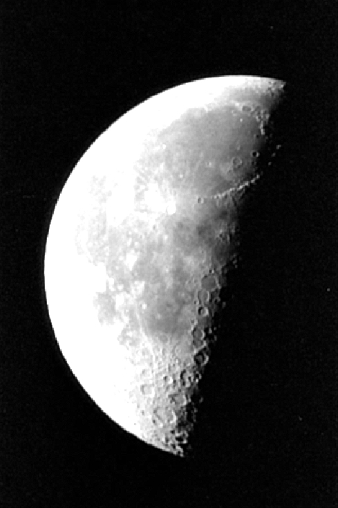
1. Read and display image moon.tif in gray-levels. What is the image format? How many quantization levels are used to represent this image?

![[zoom...]](javascript:window.open(%22../res/Figure_C1_1.jpg%22,%22_blank%22,%22width=%22+Math.min(800,screen.availWidth)+%22,height=%22+Math.min(600,screen.availWidth)+%22,left=%22+(screen.availWidth-800)/2+%22,top=%22+(screen.availHeight-600)/2+%22,scrollbars=yes,resizable=yes%22)?void(0):void(0))
moon.tif corresponds to a gray-level monochrome image. The minimum and maximum values are 0 and 253. The pixels are therefore quantized on 8 bits. It is not an indexed image since the color table is empty.
2. Modify the pixel values of image moon.tif to display it as a negative image.
A simple method is to create a uniform matrix y of same dimension as x, whose pixels are equal to 255. We then compute the difference between y and x, and display the result.

![[zoom...]](javascript:window.open(%22../res/Figure_C2_1.jpg%22,%22_blank%22,%22width=%22+Math.min(800,screen.availWidth)+%22,height=%22+Math.min(600,screen.availWidth)+%22,left=%22+(screen.availWidth-800)/2+%22,top=%22+(screen.availHeight-600)/2+%22,scrollbars=yes,resizable=yes%22)?void(0):void(0))
The difference can only be computed after conversion of the images from their original format uint8 to the format double. The output image then needs to be back-converted to uint8 before being displayed.
3.Filtering. We consider the following bidimensionnal separable filter h(5,5):
Filter creation:
Display the frequency response (in magnitude) of this filter.
>> freqz2(h)
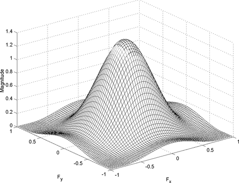
![[zoom...]](javascript:window.open(%22../res/Figure_C3_1.jpg%22,%22_blank%22,%22width=%22+Math.min(800,screen.availWidth)+%22,height=%22+Math.min(600,screen.availWidth)+%22,left=%22+(screen.availWidth-800)/2+%22,top=%22+(screen.availHeight-600)/2+%22,scrollbars=yes,resizable=yes%22)?void(0):void(0))
The frequency response of h is maximum at zero frequency (i.e. at the frequency origin). It is therefore a low-pass filter.
Filter image moon.tif by computing the convolution product with h(5,5) and display the result.

![[zoom...]](javascript:window.open(%22../res/Figure_C4_1.jpg%22,%22_blank%22,%22width=%22+Math.min(800,screen.availWidth)+%22,height=%22+Math.min(600,screen.availWidth)+%22,left=%22+(screen.availWidth-800)/2+%22,top=%22+(screen.availHeight-600)/2+%22,scrollbars=yes,resizable=yes%22)?void(0):void(0))
We now consider the filter g:
Display its frequency response:
>> freqz2(g)
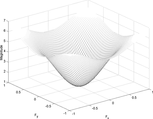
![[zoom...]](javascript:window.open(%22../res/Figure_C5_1.jpg%22,%22_blank%22,%22width=%22+Math.min(800,screen.availWidth)+%22,height=%22+Math.min(600,screen.availWidth)+%22,left=%22+(screen.availWidth-800)/2+%22,top=%22+(screen.availHeight-600)/2+%22,scrollbars=yes,resizable=yes%22)?void(0):void(0))
and apply the filter to the output image from the last step.
![[zoom...]](javascript:window.open(%22../res/Figure_C6_1.jpg%22,%22_blank%22,%22width=%22+Math.min(800,screen.availWidth)+%22,height=%22+Math.min(600,screen.availWidth)+%22,left=%22+(screen.availWidth-800)/2+%22,top=%22+(screen.availHeight-600)/2+%22,scrollbars=yes,resizable=yes%22)?void(0):void(0))
4. What conclusion can we draw from this last point?
We observe that the details and more particularly the crater contours have been highlighted by this later filtering, while they had been attenuated by the first filtering.
This example illustrates a technique used in image enhancement called « unsharp masking ».