Relationships between radiometric quantities
Introduction
Some of the basic relationships are introduced below, that may help transfer from one radiometric quantity to another, in case the radiation is propagating through an homogeneous medium, i.e. some medium of constant refractive index. These relationships are applicable to spectral quantities in case of spectrally wide radiations, or to the spectrally integrated quantities if the radiation is monochromatic. They are valid wavelength by wavelength but they can also be applied to spectrally integrated quantities of non-monochromatic radiations, if the geometry of the radiated beam is independent of wavelength.
In order to keep mathematic expressions as simple as possible, no mention will be made of the wavelength, nor or of the case under consideration (spectral or spectrally integrated quantities). Furthermore, the propagating medium will be supposed to be perfect (vacuum), the influence of an material medium being treated in Part C.1.
Flux and intensity (quasi point sources)
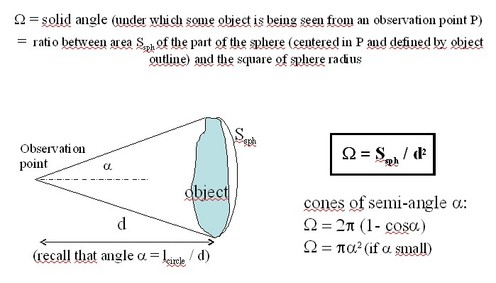
As was mentionned in the previous paragraph, the radiometric quantity that is well fitted to describe radiation from a point source or a source of unknown area is its intensity I, starting from the definition of intensity, the flux Φ (Ω) radiated by a source of intensity I inside a solid angle Ω, (over which the intensity is supposed to be constant) is (figure 5) :
![[zoom...]](javascript:window.open(%22../res/Fig_05_1.jpg%22,%22_blank%22,%22width=%22+Math.min(800,screen.availWidth)+%22,height=%22+Math.min(600,screen.availWidth)+%22,left=%22+(screen.availWidth-800)/2+%22,top=%22+(screen.availHeight-600)/2+%22,scrollbars=yes,resizable=yes%22)?void(0):void(0))
If a point source is illuminating a planar surface of area Sreceiver at a distance d with an incidence angle θ' , the solid angle Ω under which the surface is being seen from the source is given by :
and this surface receives the following flux from the source :
The resulting irradiance of the surface is proportional to the source intensity, to the cosine of the incidence angle (or obliquity factor) and inversely proportional to the square of the distance between the source and the receiving surface (« Bouguer's law ») :
At a given distance from the source, the plane of maximum irradiance is the one that is perpendicular to the incoming rays (« normal incidence »).
Flux and radiance (case of a pencil of light, or quasi collimated beam)
If the source cannot be considered as a point source, we have seen that its radiation at each point and towards each direction in space is best described by its radiance L Starting from the definition of radiance given above, one will write that the flux being radiated by the source through a small diaphragm of area S inside a small solid angle Ω centered along an axis normal to that diaphragm is given by :
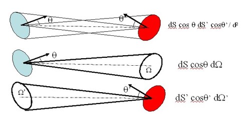
The above configuration, geometrically defined by a (small) diaphragm and a small solid angle directed along its normal, corresponds to an elementary propagation channel, called « pencil of light ». If the diaphragm (or the surface of the emitter in case the emitter is acting as the diaphragm), is not normal to the pencil axis, let θ be the angle between the pencil axis and its perpendicular : then, the projected, or apparent area of the diaphragm along the axix of the pencil is Sapp(θ)=Scosθ and the flux being radiated along that pencil of light is :
A pencil of light, or an elementary propagation channel defined by a diaphragm (of area S) and some small solid angle along an axis at angle θ with respect to the diaphragm normal, is specified by its geometrical extent G=SΩcosθ in m2 sr.
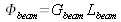
Hence, a pencil of light propagates an amount of flux that is the product of its geometrical extent by its radiance.
One may also construct a pencil of light by way of two small diaphragms, of areas respectively equal to S and S', separated from each other by a distance d (such that S and S' << d2) and with their normals at angles θ et θ' with the axis joigning the centers of the diaphragms. In any case, the geometrical extent of a pencil may be expressed by either one of the three following formulas, which are equivalent (figure 6) :
where Ω' is the solid angle under which the second diaphragm observes the first one. For this expression to apply, each point of S must illuminate the whole area of S' .
![[zoom...]](javascript:window.open(%22../res/Fig_06_1.jpg%22,%22_blank%22,%22width=%22+Math.min(800,screen.availWidth)+%22,height=%22+Math.min(600,screen.availWidth)+%22,left=%22+(screen.availWidth-800)/2+%22,top=%22+(screen.availHeight-600)/2+%22,scrollbars=yes,resizable=yes%22)?void(0):void(0))
One can deduce from above that the irradiance of an elementary area being illuminated under an incidence angle θ' by a pencil of light of radiance L inside a (small) solid angle Ω' is the following :
Flux and radiance (radiation propagating along an extended beam of constant radiance)
What happens when one start increasing the divergence of a pencil of light, without modifying the emitting area nor its radiance? The pencil of light, which is narrow to start with, is said to be transformed into a finite or extended beam of light.
The flux being radiated through an extended beam of light is obtained by adding all the fluxes that propagate along each of the elementary pencils, or channels, making up the finite beam. The geometrical extent of the beam is also obtained by adding those of its elementary pencils. Let us consider a beam of light as being made up of elementary pencils exiting from the same diaphragm with all with the same divergence ; one can easily realize that, even though they have the same initial diaphragm and the same divergence, all these pencils don't have the same geometrical extent : indeed, the geometrical extent of a given pencil is decreasing as the pencil get further and further away from the normal to the emitting surface, because the apparent area of the emitter is Scosθ. One may conclude from this elementary observation that the geometrical extent of an extended beam is no more equal to the product of its emitting area by its solid angle, as is the case for its central pencil, centered along its axis.
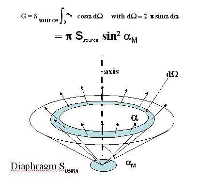
If the radiance is constant all over the geometry of the beam, the flux that propagates inside the beam is given by the following expression, where G, the geometrical extent of the beam, must be specifically computed for the configuration at hand :
Values of geometrical extents for beams of finite size and divergence have been computed for most of simple shapes : below, the result is given concerning a beam made up of a plane emitter that radiates light inside a circular cone of semi angle
 centered along its normal (figure 7) :
If a planar source is radiating over a half-space, i.e. over
 sr, the geometrical extent of its beam is:
In a similar manner, the geometrical extent of a beam that is being focused down onto a planar surface (such as that of a detector) of area Sdét , inside a cone of half angle
 centered along the axis of the surface, is the following :
If the incident beam is hemispheric
 , its geometrical extent is then :

![[zoom...]](javascript:window.open(%22../res/Fig_07_1.jpg%22,%22_blank%22,%22width=%22+Math.min(800,screen.availWidth)+%22,height=%22+Math.min(600,screen.availWidth)+%22,left=%22+(screen.availWidth-800)/2+%22,top=%22+(screen.availHeight-600)/2+%22,scrollbars=yes,resizable=yes%22)?void(0):void(0))
If the radiance is not constant inside the beam, one can no longer write
 . Then, there is not so much interest in defining the geometrical extent of the beam because this parameter does not intervene as such into the evaluation of the flux being radiated along that beam.