Periodical microbenders
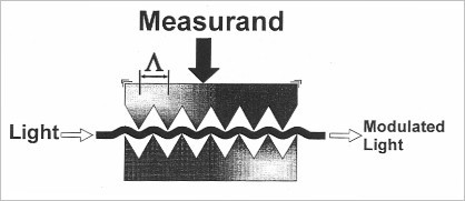
Figure 1 shows a sensor going by the periodical microbenders' principle. This technique relies on two phenomenons: the first one is creating leakages in an optical fiber as a result of small radius of curvature, the second one is the resonance effect thanks to the periodicity of the microbenders which will make the coupling of two modes possible. The curve will enable the light to come out of the fiber's core and create leakages, either by bringing out a portion of the fundamental mode or by redistributing the intensity each mode carries to the cladding modes or to the leaky mode. The periodic structure will act as a diffraction grating coupling preferentially in a cladding mode. The intensity of the coupling and so of the leakage in the intensity of the transmitted signal will be proportional to the power of these microbenders.
The coupling made through this method has been thoroughly studied in numerous books (cf [5] and [6]). To define the period of the microbenders, we can either use the network equation or the coupled mode theory, the results are similar. Then it is easy to determine the pitch as we know the characteristics of the cladding mode and conversely. The formula between the parameters is:
where
 and
and
 are respectively the constant of propagation of the fundamental mode and of the cladding mode in which the light will be coupled,
 is the pitch of the microbenders.
![[zoom...]](javascript:window.open(%22../res/Fig_01_1.jpg%22,%22_blank%22,%22width=%22+Math.min(800,screen.availWidth)+%22,height=%22+Math.min(600,screen.availWidth)+%22,left=%22+(screen.availWidth-800)/2+%22,top=%22+(screen.availHeight-600)/2+%22,scrollbars=yes,resizable=yes%22)?void(0):void(0))
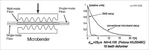
As it is above-mentioned, it is possible to create propagation leakages just by applying a definite radius of curvature to the fiber; you can use this only effect to make a sensor. Since the leakages generated by coupling to superior modes are low in monomode fibers, you can resort to a multimode fiber in the sensitive area to increase this effect, as shown on Figure 2. This sensor is a hybrid structure formed by a segment of a monomode fiber, a fragment of a multimode fiber and another fragment of a monomode fiber. The injection of the monomode fiber in the multimode fiber will generate an injection in different modes depending on the type of multimode fiber (gradient index or stepped index) and on the positioning of the two fibers. The effect of one or several curves will change the intensity transmitted by each mode. Finally, passing through the monomode fiber will only select the light transmitted by the first modes. As Figure 2 shows, the sensitivity of the hybrid structure is far higher than the sensitivity of the structure which is only made of monomode fiber.
![[zoom...]](javascript:window.open(%22../res/Fig_02_1.jpg%22,%22_blank%22,%22width=%22+Math.min(800,screen.availWidth)+%22,height=%22+Math.min(600,screen.availWidth)+%22,left=%22+(screen.availWidth-800)/2+%22,top=%22+(screen.availHeight-600)/2+%22,scrollbars=yes,resizable=yes%22)?void(0):void(0))
based on [7]
The sensor made of one or several curves can be used to measure:
-
displacement, by letting one of the two blocks free.
-
pressure, by using an elastic membrane to let one of the two blocks move [8].
-
strain; several configurations are possible with a single curve and a fiber maintained on the piece to measure, or with microbenders, whose distance between one another depends on the strain to detect [9], [10].
-
vibration; one of the two blocks is linked up to a mass whose acceleration makes it move [11].
-
temperature, by using the thermal properties of the different materials [12].