Two-wave interferometers
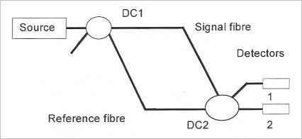
The most common form of two-wave interferometers is the Mach-Zehnder configuration shown on Figure 7. The source is coupled in a monomode optical fiber, the amplitude is divided into two fibers after being passed in a directional coupler DC1. One of the fibers is to be the reference wave (i.e. the reference fiber) whereas the other is the modulated wave (i.e. the signal fiber). Then the fibers are combined again with another directional coupler DC2. All you have to do then is plugging a photodetector in one of the outputs of the DC2 to get an electrical signal which will be proportional to the incident optical power.
![[zoom...]](javascript:window.open(%22../res/Fig_07_1.jpg%22,%22_blank%22,%22width=%22+Math.min(800,screen.availWidth)+%22,height=%22+Math.min(600,screen.availWidth)+%22,left=%22+(screen.availWidth-800)/2+%22,top=%22+(screen.availHeight-600)/2+%22,scrollbars=yes,resizable=yes%22)?void(0):void(0))
We can demonstrate [24] that the intensities seen by the photodetectors 1 and 2 can be written as:
and
where
 and
and
 are the phases of the signal and reference waves, I0
is the average intensity and V is the interferences' visibility. The visibility depends on the relative intensities of both signal and reference waves. The best visibility can be obtained when the intensities are identical and the difference of optical path between the signal and reference waves is smaller than the length of coherence of the source. Under these circumstances, the visibility is equal to 1. Otherwise, the visibility generally varies between zero and one. It is important to note that the two intensities I1 and I2
are in phase opposition and that their sum is constant. The access to both of the outputs can make it possible to mitigate the possible fluctuations of the source.
are the phases of the signal and reference waves, I0
is the average intensity and V is the interferences' visibility. The visibility depends on the relative intensities of both signal and reference waves. The best visibility can be obtained when the intensities are identical and the difference of optical path between the signal and reference waves is smaller than the length of coherence of the source. Under these circumstances, the visibility is equal to 1. Otherwise, the visibility generally varies between zero and one. It is important to note that the two intensities I1 and I2
are in phase opposition and that their sum is constant. The access to both of the outputs can make it possible to mitigate the possible fluctuations of the source.

![[zoom...]](javascript:window.open(%22../res/Fig_08_1.jpg%22,%22_blank%22,%22width=%22+Math.min(800,screen.availWidth)+%22,height=%22+Math.min(600,screen.availWidth)+%22,left=%22+(screen.availWidth-800)/2+%22,top=%22+(screen.availHeight-600)/2+%22,scrollbars=yes,resizable=yes%22)?void(0):void(0))
Figure 8 shows the Michelson interferometer which is a variant of the Mach-Zehnder one. Both reference and signal fibers are ended by reflectors which reflect the light on itself. The directional coupler DC combines and divides the beams at the same time. The sensitivity of this interferometer is twice as high as Mach-Zehnder interferometer's because the signal passes twice in the sensitive area. However, this configuration has an important disadvantage, since it reflects the signal towards the source. It can generate instabilities in the source area [25] especially when using laser diodes. In practice, in order to avoid this problem, people add an optical isolator just after the source, this device only lets the light pass in one direction, so that it prevents any light coming back to the source. The optical isolators use the Faraday effect to rotate the polarization and a polarizer to block the wave or not. Another disadvantage of this coming back to the source is not being able anymore to access to the intensity in phase opposition and to easily mitigate the fluctuations of the source.
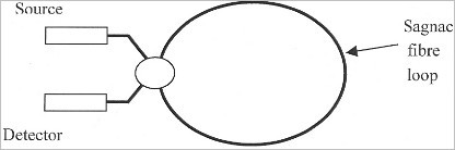
The Sagnac interferometer shown in Figure 9 is another kind of two-wave interferometers. It has essentially been created to measure the angular speed, like in the gyroscope's case [26].
![[zoom...]](javascript:window.open(%22../res/Fig_09_1.jpg%22,%22_blank%22,%22width=%22+Math.min(800,screen.availWidth)+%22,height=%22+Math.min(600,screen.availWidth)+%22,left=%22+(screen.availWidth-800)/2+%22,top=%22+(screen.availHeight-600)/2+%22,scrollbars=yes,resizable=yes%22)?void(0):void(0))
The signal and reference waves are propagating in the same fiber and rotate clockwise and anticlockwise into a fiber loop. At first sight, the two waves seem to propagate in the same path and so to always be in phase, and that is true if we have reciprocal effects. However non-reciprocal effects can make phase differences, notably angular speed [27], a magnetic field [28] or a dynamic measurand [29]. Let's take as an example the effect of a dynamic and mechanical strain near one of the tips of the fiber loop. At a given moment, the signal and reference waves coming to the directional coupler to interact will not see the same strain, so that the phase difference will not be null anymore.