Polarimetric sensors
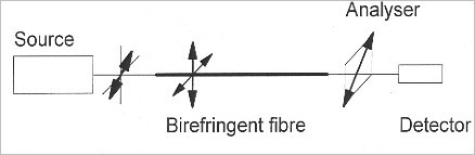
In most cases, polarimetric sensors use a linearly polarized source which is injected at a 45 degree angle from the main axes of the birefringent fiber so that the two propagating ways (slow and fast) should be similarly excited.
![[zoom...]](javascript:window.open(%22../res/Fig_18_1.jpg%22,%22_blank%22,%22width=%22+Math.min(800,screen.availWidth)+%22,height=%22+Math.min(600,screen.availWidth)+%22,left=%22+(screen.availWidth-800)/2+%22,top=%22+(screen.availHeight-600)/2+%22,scrollbars=yes,resizable=yes%22)?void(0):void(0))
Using a half-wave plate can simplify a lot adjusting the orientation of the input polarization. At the output of the birefringent fiber, an analyzer (i.e. a polarizer) is placed in front of the detector to determine the state of polarization (cf Figure 15). The measurand will make the polarization rotate, so the intensity seen by the detector will vary. This assembly's drawback is its sensitiveness to the intensity variations of the source or of the injection. Using a Wollatson prism which separates the light into two orthogonally polarized beams enables you to avoid this problem, by using techniques like the ones detailed in the Periodical Micro-curves chapter and in the Evanescent field chapter. However bringing the prism into the line of the two detectors and of the main axes of the fiber is quite tricky.
We will now use Jones matrices to analyze the component. As we have already mentioned it, the two birefringent fiber's propagating modes which are orthogonally polarized are similarly excited. In this case, the electric field can be written as:
The electric field which is incident on the detector can be described as:
where A and B are respectively the Jones matrix of the analyzer and of the birefringent fiber. The fiber can be seen as the phase plate which modifies the phase difference between the two polarizations. The B matrix can be described as:
where
 is the average phase difference and
 is the phase difference between the two polarizations. This phase difference is produced by the propagation of light through the fiber.
In the specific case of an analyzer at a 45° angle from the fiber's main axes, the A matrix is written as:
The intensity after the analyzer will be:
where I0 is the total output power. Consequently, as the previous equation shows, changing the state of polarization will modify the intensity seen by the detector and make a sinusoidal signal. The previous equation is similar to the equations (1) and (2) which describe two-wave interferometry. Some measuring techniques can be transposed to improve the sensitivity.