Polarimetric current sensors
Here we will study the case of a polarimetric current sensor. This kind of sensors can be used for measuring classic measurands (like temperature, mechanical strain or pressure), however their field of expertise is currents or tensions measuring.
The aim when using these sensors is to assess the intensity of the current passing in a conductor by measuring the density of the magnetic flux created around the conductor by the charges' displacements.
The density of the magnetic flux is given by the rotation of the polarization state of the light wave travelling in the fiber or in the magneto-optical material. This rotation is due to the magneto-optical effect which is proportional to the length of interaction (L) and to the Verdet constant (
 ) of the material used for making the sensor. The angular rotation
 (in degrees) of the polarization of the wave travelling in the component is given by:
where B is the magnetic induction (Tesla) which is a function of the current travelling in the conductor and of its geometry.
Different methods can be used to measure the angle
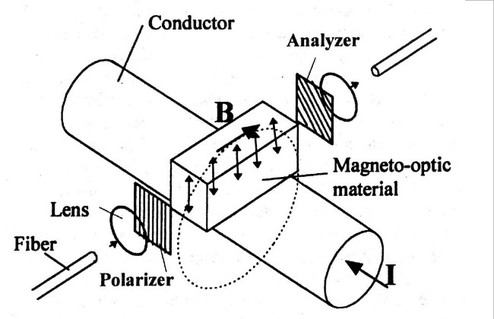
. The basic method is, first, to make the depolarized light pass through the polarizer. Then this polarized wave is modified by the influence of the magnetic field and eventually this rotation is converted into a modification of the intensity by the analyzer placed in front of the detector (see Figure 19):
![[zoom...]](javascript:window.open(%22../res/Fig_19_1.jpg%22,%22_blank%22,%22width=%22+Math.min(800,screen.availWidth)+%22,height=%22+Math.min(600,screen.availWidth)+%22,left=%22+(screen.availWidth-800)/2+%22,top=%22+(screen.availHeight-600)/2+%22,scrollbars=yes,resizable=yes%22)?void(0):void(0))
The emitted intensity can be described as:
whereI0 is the source's intensity.
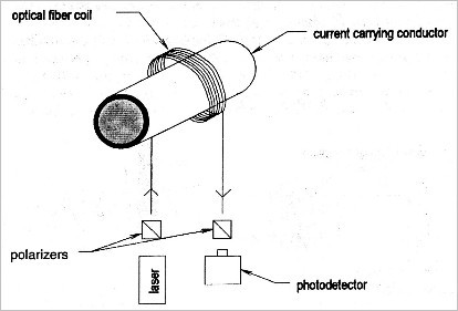
The easiest way to insert an optical fiber current sensor is shown on Figure 20:
![[zoom...]](javascript:window.open(%22../res/Fig_20_1.jpg%22,%22_blank%22,%22width=%22+Math.min(800,screen.availWidth)+%22,height=%22+Math.min(600,screen.availWidth)+%22,left=%22+(screen.availWidth-800)/2+%22,top=%22+(screen.availHeight-600)/2+%22,scrollbars=yes,resizable=yes%22)?void(0):void(0))
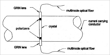
The magneto-optical material used here is the optical fiber itself. This solution is very easy to perform and very cheap. The main drawback is the low Verdet constant of the silica fiber (≈8x10⁻⁶ rad/A) which is significantly lower than other commonly used crystalline materials' ones. It is possible to slightly increase the sensitiveness of this configuration by performing a round-trip in the area where the magnetic field is, either by adding a mirror at the fiber's extremity, or by using a configuration similar to a Sagnac interferometer's. Of course adding a coupler is necessary. Another possibility is to use a material which has a high Verdet constant like in Figure 21:
![[zoom...]](javascript:window.open(%22../res/Fig_21_1.jpg%22,%22_blank%22,%22width=%22+Math.min(800,screen.availWidth)+%22,height=%22+Math.min(600,screen.availWidth)+%22,left=%22+(screen.availWidth-800)/2+%22,top=%22+(screen.availHeight-600)/2+%22,scrollbars=yes,resizable=yes%22)?void(0):void(0))
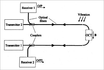
The optical sensors' sensitivity to variations of temperature and to vibrations has lead researchers to design more complex assemblies. One of the possible assemblies for mitigating disturbances is shown on Figure 22:
![[zoom...]](javascript:window.open(%22../res/Fig_22_1.jpg%22,%22_blank%22,%22width=%22+Math.min(800,screen.availWidth)+%22,height=%22+Math.min(600,screen.availWidth)+%22,left=%22+(screen.availWidth-800)/2+%22,top=%22+(screen.availHeight-600)/2+%22,scrollbars=yes,resizable=yes%22)?void(0):void(0))
Two independent light sources are injected and travel in opposite directions. The rotation of the polarization state depends on the way the wave travels in the sensor, however the intensity of the two sources is not affected. Consequently, we can use signals to correct the vibration measured as shown on Figure 23. We can see that mitigating significantly improves the measuring of low current, but for high intensities it is not really necessary.
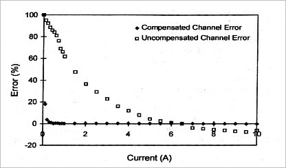
![[zoom...]](javascript:window.open(%22../res/Fig_23_1.jpg%22,%22_blank%22,%22width=%22+Math.min(800,screen.availWidth)+%22,height=%22+Math.min(600,screen.availWidth)+%22,left=%22+(screen.availWidth-800)/2+%22,top=%22+(screen.availHeight-600)/2+%22,scrollbars=yes,resizable=yes%22)?void(0):void(0))
(according to [2])
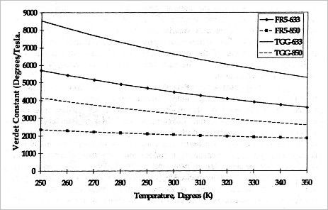
The errors due to temperature come, most of the time, from the materials' big variations of the Verdet constant, as the curves of Figure 24 show.
In Figure 24 we can see that both materials FR5 (Faraday Rotator 5 glass) and TGG (Terbium Galium Grenat) are very sensitive to temperature. Nevertheless, this sensitiveness can be reduced by using an appropriate wavelength. If we want to make an optical current sensor with a low sensitiveness to temperature, FR5 material is right provided that we keep
 even if its Verdet constant is lower than TGG's one.
![[zoom...]](javascript:window.open(%22../res/Fig_24_1.jpg%22,%22_blank%22,%22width=%22+Math.min(800,screen.availWidth)+%22,height=%22+Math.min(600,screen.availWidth)+%22,left=%22+(screen.availWidth-800)/2+%22,top=%22+(screen.availHeight-600)/2+%22,scrollbars=yes,resizable=yes%22)?void(0):void(0))
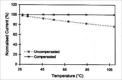
If we know how the material used for the transducer reacts to temperature variations, it is easy to compensate the measuring. In the reference [1] the authors decided to use a Bragg grating temperature sensor and discovered a compensation range from 20°C to 120°C, as it is shown on Figure 25:
![[zoom...]](javascript:window.open(%22../res/Fig_25_1.jpg%22,%22_blank%22,%22width=%22+Math.min(800,screen.availWidth)+%22,height=%22+Math.min(600,screen.availWidth)+%22,left=%22+(screen.availWidth-800)/2+%22,top=%22+(screen.availHeight-600)/2+%22,scrollbars=yes,resizable=yes%22)?void(0):void(0))
(according to [43])