Experimental setup
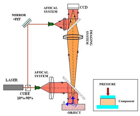
Figure 1 shows a speckle interferometry setup used to study the watertightness of an industrial connector of area 15×23 mm².
![[zoom...]](javascript:window.open(%22../res/etude_cas_fig_01_1.jpg%22,%22_blank%22,%22width=%22+Math.min(800,screen.availWidth)+%22,height=%22+Math.min(600,screen.availWidth)+%22,left=%22+(screen.availWidth-800)/2+%22,top=%22+(screen.availHeight-600)/2+%22,scrollbars=yes,resizable=yes%22)?void(0):void(0))
The interferometer is composed of a laser source, λ=0.6328μm, which is separated into two beams with a ratio 10%-90%. The beam illuminating the object is collimated and at normal incidence to the object surface. The object diffracts a wave towards the image sensor. The imaging objective, of f-number N=8, images the object surface on the detector with a transverse magnification of gx. The detector is a CCD (Charge Coupled Device) camera containing 572×768 pixels of size px ×py =8.6×8.6μm2. The detector encodes the image with 8 bits and each pixel has a full well capacity of Ne=30000 electrons and an electronic noise of 10 electrons.
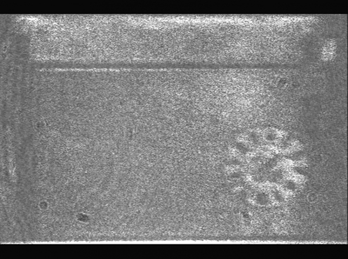
The reference beam interferes with the object beam at the detector. On the reference beam path, a mirror is mounted on a piezo-electric device of sensitivity spzt =0.25μm/V. This sensitivity has been estimated with a precision of σpzt/spzt=5%. The image of the object, observed through the objective, is superimposed with the speckle pattern due to coherent illumination and to the natural roughness of the object. This image is shown on figure 2.
![[zoom...]](javascript:window.open(%22../res/etude_cas_fig_02_1.jpg%22,%22_blank%22,%22width=%22+Math.min(800,screen.availWidth)+%22,height=%22+Math.min(600,screen.availWidth)+%22,left=%22+(screen.availWidth-800)/2+%22,top=%22+(screen.availHeight-600)/2+%22,scrollbars=yes,resizable=yes%22)?void(0):void(0))
This image is of bad quality because of the speckle grains which constitute a coherent noise of random fluctuation. However, the random pattern encodes for a (random) interference signal since the speckle interferes with the reference wave. The signal registered on the sensor takes the following expression:
The optical phase
 is random and uniformly distributed over
 . In the sensor plane, the speckle has a (statistical) mean length given by:
 in the plane (x , y)
 along the propagation axis.
The two numbers constitute the transverse and axial correlation lengths of the speckle in the image plane.
Using the numerical value, gy
=-0.28, we obtain Φxy
=7.9μm and
 . The size of a speckle grain in the image plane is therefore on the order of 8μm, and we have approximately one speckle grain per pixel. This value indicates that the maximum speckle shift that can be measured with this process is smaller than 8μm.
Considering that the random fluctuation have a correlation length equal to the pixel size, we can infer that any spatial filtering with a kernel of several pixels will strongly reduce that fluctuation.