Interference and fringe pattern demodulation
Correlation fringes
The techniques enables the visualization of the object displacements by simple geometric superposition (similarly to moiré techniques). Since the speckle patterns are registered using a CCD camera, it is possible to digitally compare reference E to deformation F . We subtract in real time the reference image to the current image and we display the modulus of the result:
Figure 3 shows the results obtained with this technique.
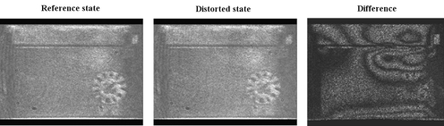
Figure 3 : image of the object
[zoom...]
![[zoom...]](javascript:window.open(%22../res/etude_cas_fig_03_1.jpg%22,%22_blank%22,%22width=%22+Math.min(800,screen.availWidth)+%22,height=%22+Math.min(600,screen.availWidth)+%22,left=%22+(screen.availWidth-800)/2+%22,top=%22+(screen.availHeight-600)/2+%22,scrollbars=yes,resizable=yes%22)?void(0):void(0))
We observe the correlation fringes, which correspond to the line of equal displacement of the structure between the two loadings.